Solving Intermittent Cable Modem Issues
(plus "loose/bad connectors" and other issues)
Version 4.4a (updated September 16, 2023)
Do you have an intermittent cable modem Internet connectivity problem?
Is your Internet connection working most of the time, but dropping sporadically
and periodically (like only during the middle of every day)?
Is VoD on cable set top boxes also impacted at the same time?
Check to see if cable modem channel "Suckout" and/or "Loose/Bad Connectors" are the problem.
These are things YOU can check (and with loose connectors, fix) yourself.
Even seemingly minor 'loose connectors', or connectors not screwed on fully, or improperly installed F-connectors
-- can surprisingly be a major cause of intermittent cable modem issues (see video right)
The bottom line:
Many cable modem Internet problems are ultimately caused by bad/loose cable/connector issues, which
you can solve youself. And that is what the rest of this paper is all about -- providing you with
the information needed to help you to solve cable modem Internet connectivity problems yourself.
FIRST STEP:
The first step is to confirm that the cable modem (and not something else) is actually having problems.
This step is important, because if you are experiencing Internet connectivity issues,
but the cable modem log shows NO issues, maybe the problem is with your
router, Wi-Fi, or something else?
But also be practical. If you don't notice Internet issues, don't worry that much about
what you find in the cable modem diagnostic web pages.
Cable Modem Diagnostics Webpage:
ALL cable modems should have a diagnostic webpage, often at http://192.168.100.1,
or http://192.168.0.1 that
displays all sorts of invaluable information like (1) downstream channels/power/SNR, (2) upstream channels/power,
(3) event logs, etc. that will assist in finding problems and confirming fixes.
TIP: Google the brand and model number of your modem and 'manual' (eg: "Netgear CM1000V2 manual") to
find the manual for your modem, which should disclose the IP address to use to get to the diagnostics
webpage for your cable modem.
TIP: For unknown reasons, when I manually power cycle my Netgear CM1000 cable modem (on Comcast), after reboot,
the diagnostics web page is inaccessible. However, if I disconnect the RG6 cable from the back of the modem,
and reconnect it a minute later, the cable modem diagnostics web page can once again be accessed
(and of course, you need to ignore some of the errors in the event log caused by disconnecting
the RG6 cable).
►Event Log:
First, find and examine the cable modem event log. You want to determine if your cable modem
is complaining about anything 'critical' on a regular basis. Infrequent messages are nothing
to worry about. But frequent or periodic error messages (like every day) indicates that something is likely wrong.
Ideally, you want an event log that is always 'empty' -- meaning that the cable modem
is in continuous/reliable communication with the CMTS ("Cable Modem Termination System"
- the cable company equipment that your cable modem communicates with).
You are looking for any regular/frequent critical/warning log entries like the following:
- Started Unicast Maintenance Ranging - No Response received - T3 time-out
- No Ranging Response received - T3 time-out
- T4 time out
- Dynamic Range Window violation
- RNG-RSP CCAP Commanded Power Exceeds Value Corresponding to the Top of the DRW
- RNG-RSP CCAP Commanded Power in Excess of 6 dB Below the Value Corresponding to the Top of the DRW
But also, be practical. Errors in the event log are only 'bad' if you notice an impact on
Internet connectivity. For me, the errors made business video conference calls unworkable
and VoD on two-way cable boxes in the house would error out in the middle of watching programs.
Very annoying and very impactful.
Again, you are looking for frequent (every day or so) critical errors in the cable modem event log.
It is generally NOT considered a problem to see one critical error a week, or regular 'notice'
messages in the event log.
After bypassing all house wiring (section below), the expectation is that
frequent messages in the event log should 'go away'.
If not, this indicates an issue 'somewhere' with the cable company.
Downstream Power (dBmV)

|
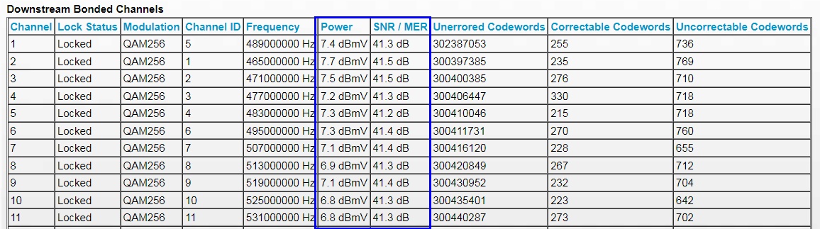
►Downstream "Power":
Indicates how powerful the signal is from the CMTS to your cable modem.
The 'ideal' target value is 0 dBmV. Higher (positive) numbers means
a more powerful signal. Lower (negative) numbers mean a less powerful signal. The best
range for a cable modem to operate in is from -7 dBmV to +7 dBmV, but the cable industry
says cable modems should still work 'fine' within a range from -15 dBmV and +15 dBmV.
If power levels are low (less than -11 dBmV), investigate why and fix. Is your modem
behind too many splitters? At the cable demarc location, there should be a single 2-way
splitter feeding (1) the cable modem and (2) the rest of the house via another passive
splitter. See section far below on a 'powered amp' alternative.
If power levels are too high, or 'hot' (greater than +15 dBmV), contact your cable company to resolve.
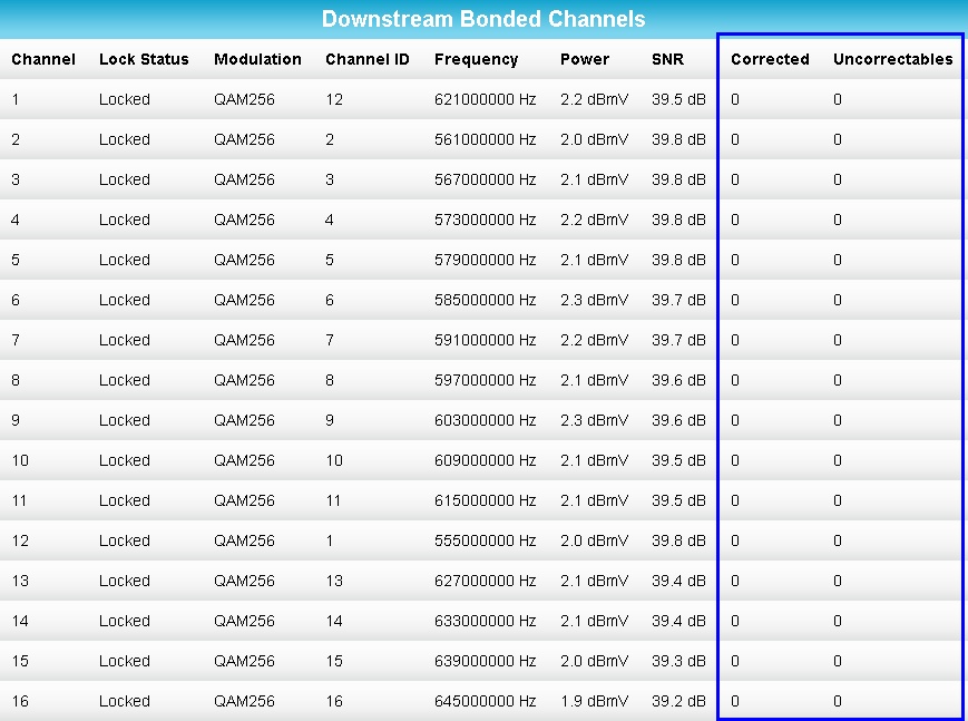
Also, all downstream channels should have 'similar' "Power" and "SNR" values (all 'Power' within 3 dB of
each other and all 'SNR' within 3 dB of each other). If not, this 'imbalance' may indicate a
"suckout" problem (see section further below). Here is a 'good' example with no problems:
After bypassing all house wiring (connecting the cable modem to the cable
demarc location; section below),
the expectation is that downstream power should be within the 0 dBmV to +15 dBmV range.
If not, this (likely) indicates an issue 'somewhere' with the cable company
(namely, why is the cable company not providing a strong signal to the home).
Downstream SNR (dB)

|
►Downstream "SNR":
The higher the number, the less 'noise' there is (relative to the signal)
-- so the better the 'signal quality'.
For QAM256 (the modulation seen in the example table above), you want to see a minimum SNR of 33.
But higher than '33' is very typical, like in the 37 to 39 range (like in table above, it is above 41,
which is excellent).
SNR is an acronym for "Signal to Noise Ratio".
MER is an acronym for "Modulation Error Ratio".
SNR is "how many dB above the 'noise floor' the signal is" and effectively indicating
how well the signal is heard above any noise.
An analogy: If you talk normally to someone at home, they can easily hear/understand you because there
is virtually no noise -- so the SNR is very high. However, if you talk normally with someone at
a bar, they can barely hear/understand you because there is a lot of background talking
(noise) -- so the SNR is very low. You need to speak much louder to get 'the signal' above
the 'noise floor'.
After bypassing all house wiring (section below), the expectation is that
downstream SNR should be excellent.
If not, this indicates an issue 'somewhere' with the cable company.
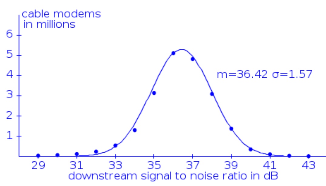
How does your Downstream SNR compare to everyone else? Comcast in 2013
published
the Downstream SNR values seen in a sample of 20 million cable modems and got the following graph.
The bottom line is that if your SNR is above 36.4, then your SNR is "above average".
Upstream Power (dBmV)

|
►Upstream Power:
The lower the number the better (within reason). This is the
power level that the CMTS has instructed the cable modem to transmit at in order for the
modem's signal to be received by CMTS with a power of 0 dBmV
(source).
Expect to see upstream power levels between 35 dBmV and 48 dBmV, which is 'normal'. Anything
above that and the cable modem is starting to 'shout' at the CMTS and that is undesirable
(and at some point, it no longer works well).
Here is a 'good' example with no problems:
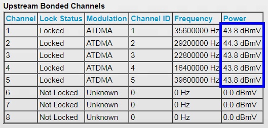
The power level for all individual upstream bonded channels should all be within 3 dB of each other. If not,
there is a problem to find. First evaluate all house wiring (see rest of this paper). If that
does not fix, contact your cable company.
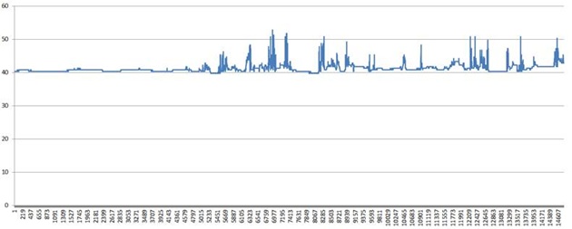
IMPORTANT: Expect "Upstream Bonded Channels" power levels to be steady/consistent
(within approximately 1 dB) throughout the entire day.
Big jumps/spikes all of a sudden of 3+ dB in any channel is NOT normal and is a
very strong indicator of problems (like bad cables, loose connectors, noise ingress, etc.
see sections below). Below is a graph of maximum upstream power seen by my cable
modem over ten days, sampled every minute. The 'spikes' in upstream power (of 8+ dB) correspond to
Internet connectivity problems, with various critical errors logged in the cable modem event log.
Notice how everything was good/flat for the first couple of days, and then got bad.
Also, now that my problems are fixed, the graph of 'Upstream Power' is now always 'flat'.
When upstream power is too high, again the question is: Is there a bad cable? Or, are there
too many splitters between the modem and the cable company? See the section far below
on powered amps.
See the section far below on the expected dB signal loss of cable length
and splitters. The cable modem needs to increase upstream power by the dB loss of all
splitters between it and the cable company. So you can immediately and instantly
improve (reduce) upstream power by finding a way to remove splitters between the modem
and the cable company.
After bypassing all house wiring (section below), the expectation is that
upstream power should be well within the 35 dBmV to 48 dBmV range.
If not, this indicates an issue 'somewhere' with the cable company.
►Correctable/Uncorrectable Codewords for downstream QAM channels: The
ultimate goal is for these numbers to be zero (or effectively zero). It is possible.
The cause of correctable/uncorrectable codewords is RF ingress, or noise, period.
So if you see these numbers increase on a regular basis (check before/after an
Internet speed test), you KNOW you have
a RF ingress (noise) problem to fix. Likely causes are bad or loose connectors,
bad cable, etc -- anywhere in the house (see the rest of this paper).
Conversely, if you see NO uncorrectable errors and effectively zero correctable codeword
errors (like 1 in 100,000,000), you know that the cables, connectors, splitters, etc
in the house are in great shape.
I have multiple locations where over an extended period of time (like a week),
there are NO 'uncorrectable' codewords (yes, none), and the number of 'correctable'
codewords is so incredibly low (one in a billion) as to effectively be zero.
But also be practical. If you see codeword errors, but are not noticing any
Internet issues, don't worry about the errors (something I have at other locations).
Please note this discussion only applies to QAM channels, not OFDM channels.
Because with OFDM channels, seeing 'correctable' codewords is normal.
After bypassing all house wiring (section below), the expectation is that
codeword errors will be effectively eliminated.
If not, this indicates an issue 'somewhere' with the cable company.
Downstream/Upstream Power Levels balancing act: Notice that how many (or few) splitters there are
between the cable modem and the cable company directly -- but inversely --
impacts both downstream and upstream power levels.
Adding a two-way splitter into the modem run will cause downstream 'power' to decrease
by 3.5 dB, but cause upstream 'power' to increase by 3.5 dB.
And conversely, removing splitters in the modem run will cause downstream power
to increase by 'X' dB, but upstream power to decrease by 'X' dB.
SECOND STEP:
The second step (after confirming a cable modem problem; section above),
is to point the finger and blame either the cable company (call the cable company to fix),
or house wiring (first, try to fix the issue yourself; as a last resort, call the cable
company for help).
But also watch out as there may be problems with both cable company
wiring AND house wiring.
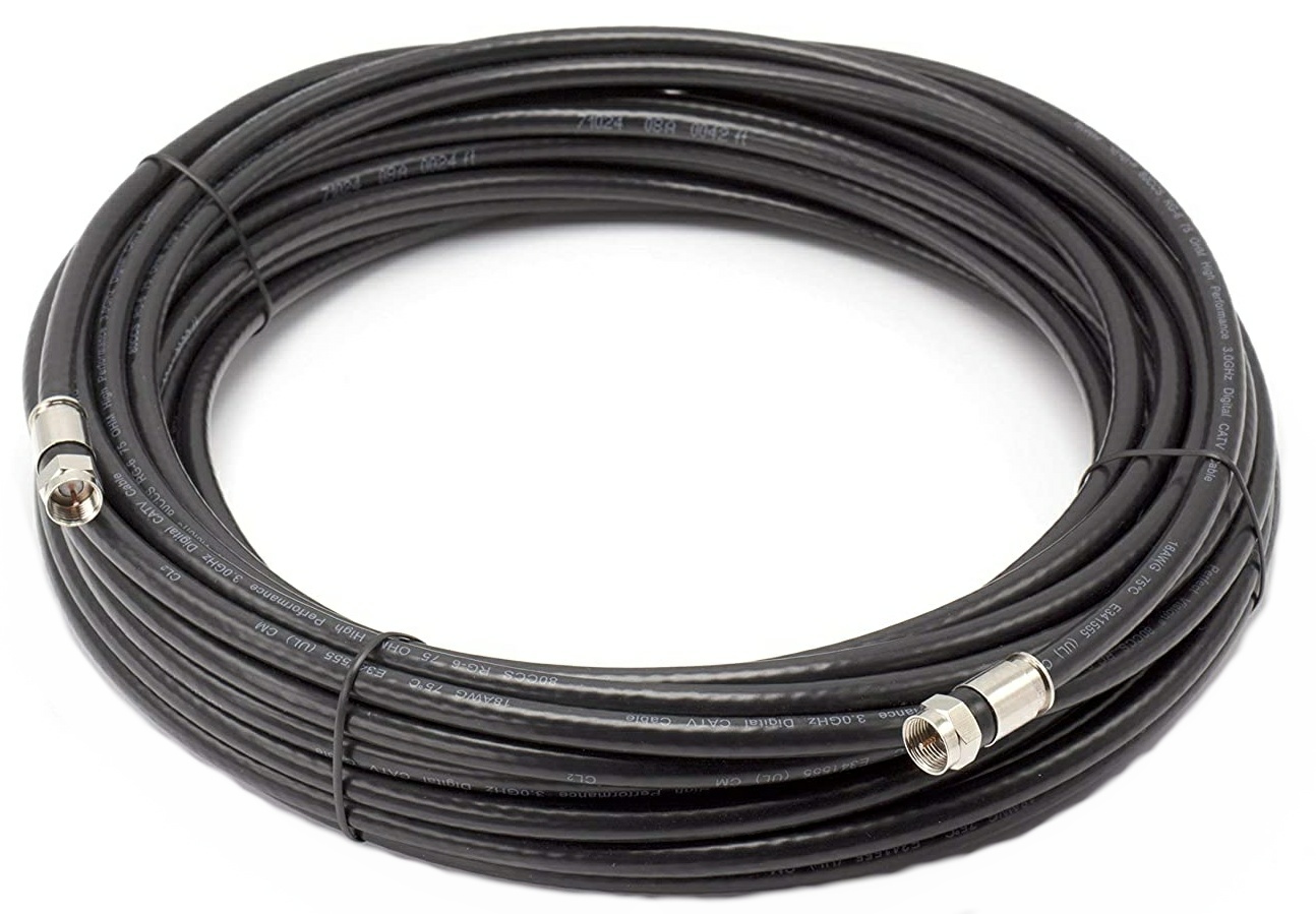
100ft RG6:
Spend $15 (Amazon) and get a high quality 100-foot indoor/outdoor tri-shield RG6 cable
(or whatever length you need to make the test below work) and connect your cable modem
directly to the cable line feeding your house
(this bypasses ALL house cabling, connectors, splitters, etc).
Note that for the duration of this test that your Internet will work,
but all other cable connected boxes will be offline.
CATV whole-house feed in the cable demarc box
|
Goal: The goal is to disconnect your entire house from the cable company, and run a
NEW (temporary) RG6 line all the way from the line feeding your house (at the cable demarc box at
the side of your house) to ONLY your modem (and nothing else) and see if the problem remains.
Do NOT use any splitters or other RG6 cable, and do not splice smaller length cables together.
You want a direct connection from your cable modem to the RG6 feed provided by the cable
company using only a single brand NEW RG6 line.
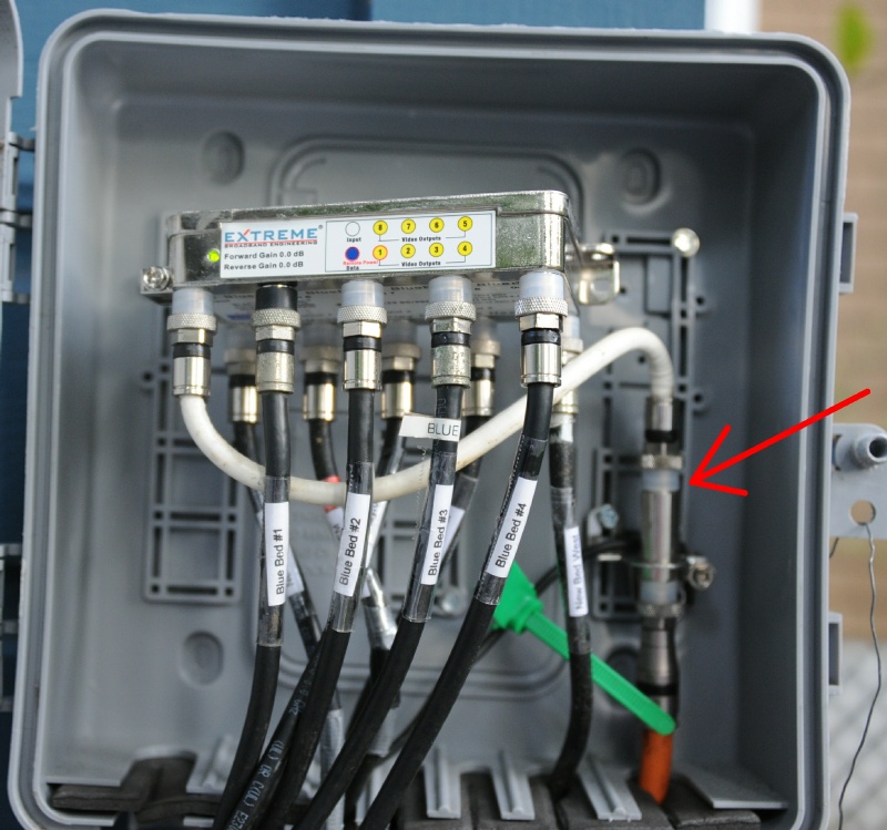
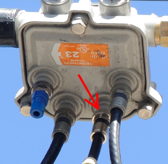
Look for a gray cable box on the outside of your house where utilities
(electrical / phone / cable / gas / etc) enter your house (the demarcation -- or 'demarc' -- location).
You should see a cable demarc box with an often thicker cable line from the cable company
(orange cable in photo upper right)
feeding into a 'ground block'
(and integrated MoCA filter; commonly installed by cable companies),
which then feeds a
line feeding the rest of your house (white cable in photo upper right). The 'disconnect/reconnection'
point is just past the 'ground block'
(for an example, see red arrow in photo upper right).
Another reason for testing using only a NEW RG6 cable from the modem to the demarc location
is to eliminate the possibility of a damaged/bad cable somewhere in the house/walls (like during
construction a nail hitting a cable line).
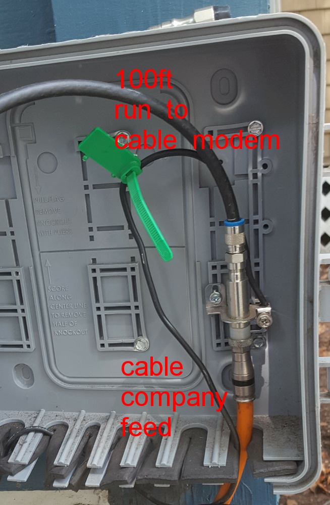
100ft run directly to cable modem
|
Possible Result One:
If your Internet problems go away (see section above to verify), then that points the finger at house
wiring as the source of the problem.
Try to fix the problem yourself first (carefully examine each cable run as per the rest of this paper).
The expectation (when your cable modem is directly connected to the cable company demarc location)
is that downstream power levels are 'high' (above 0 dBmV) and that upstream power levels are
'low' (well below 45 dBmV).
If not, is the cable company not providing proper signals to your decmarc location?!
Possible Result Two:
Or, if a problem remains (after bypassing your entire house), then you KNOW there is a
problem 'somewhere' and with the cable company (but another rare possibility is a bad cable modem).
Call the cable company to fix.
WARNING: Finding a problem 'somewhere' with the cable company does NOT eliminate the
possibility that there may ALSO be secondary issues with house CATV wiring.
This is what happened at my house. There were numerous problems, both with the cable
company wiring AND with the house cable wiring.
|
TIP: If there is a problem after bypassing house wiring, leverage that fact to
get a free tech visit to fix that problem. But when the tech arrives, tell them how
you tested and what you found, but emphasize that you also want the tech to verify
that all house wiring is OK as well.
Doing this probably would have saved me a couple of later tech visits. Because as
soon as I said I bypassed all house wiring and still found a problem, the tech ignored
all house wiring (and missed finding a secondary problem in the house).
|
"Divide and Conquer" to isolate the problem part:
In general, the "Divide and Conquer" technique is how to find
the root cause of any problem. Remove/Bypass a part (around half) of the equipment/cables/etc
and see if the problem remains. If so, repeat. If not, move to the other part.
Eventually you will be left with only the problem part.
OR, start with a working setup, and slowly add parts back in until
the problem reappears (and then blame what you just added back in). It may take some
time and patience, but you will find the problem.
This is how one person found that an improperly grounded splitter was the cause of
problems. Any 'grounding' wire connected to a splitter must be properly connected
to a grounding rod driving into the ground, and not connected to something else
(which may not itself be properly grounded).
THIRD STEP:
The third step is for YOU to inspect all in-house wiring and take action
(see sections further below) to fix problems that are found.
Inspect everything:
Regardless of the result of the 'bypass the house' test in the section above, plan to take
the time and perform a full critical inspection of every cable run everywhere, and
the connectors on those runs, especially the connectors behind wall plates (see sections
below) -- and correct any problems found.
In the process of doing this, I found a bad splice in a run through the attic space.
While there should never be splices in runs, I can only assume the run was damaged during
construction, and the only fix available was to splice the line (it was too late to install
a new run).
I also mapped all runs in my house and labeled all cables, because I wanted to confirm
that each 'run' only ran to a single location and device. Ideally, there should
be no splitters in the home feeding multiple locations/rooms/devices, but the reality
is that sometimes they can not be avoided (when a home was not properly wired when built).
When cable modem downstream power levels vary by more than 3 dB between all channels, the
problem may be something the cable industry calls "suckout".
"Suckout" Defined: A "Notch in the frequency response affecting one or more channels,
caused by loose modules, module covers, printed circuit boards, poor grounding,
and similar problems inside of active or passive device housings."
See source for this definition
and second source.
Some online comments also suggest that temperature variations, causing loose outdoor
cables to expand/contract, can also be a root cause of suckout.
Suckout Example: For my modem, I was getting a major power imbalance between downstream channels. Graphing
the "Power" level for each cable modem downstream channel
(important, sort by MHz/frequency, as the list provided by the modem will very likely be 'out of order')
showed a significant
'notch' or 'suckout' (a big dip or valley) for the first channels:
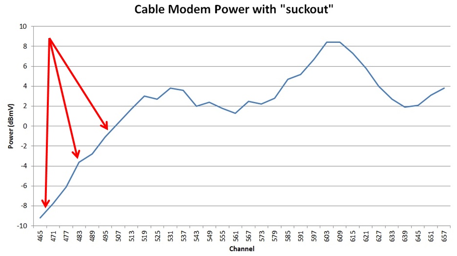
Subtract the minimum power level seen (for any/all channels) from the maximum power level seen.
From the above graph, this value is 8 - (-9) = 17. This is WAY too large. Instead,
the result should have been under 3 (much closer to zero; example below).
If you see a 'suckout' problem, even after bypassing house wiring (connecting your modem
directly to the cable company demarc location), contact your cable company.
After the fix: After the cable company fixed the 'suckout' issue, power levels (and SNR)
looked a LOT more normal (consistent/level/flat). Here is a graph of the "Power" level for each
downstream channel (by MHz) after the cable company fixed the problem:
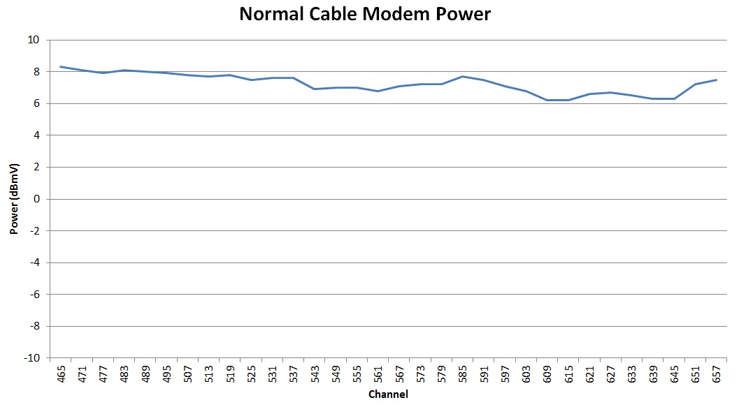
Subtracting the minimum from the maximum yields '2' -- a good result (it is under 3). The modem
at this location was a Netgear CM1000V2 using 32 bonded downstream channels.
Notice that spotting "suckout" becomes much easier with lots of bonded channels
(each channel is 6 MHz wide).
With 8 bonded channels covering only 48 MHz of spectrum you are not very likely to
notice 'suckout'. But with 32 bonded channels covering at least 192 MHz of
spectrum, spotting 'suckout' becomes much easier.
An 'F-connector' is the type/name of connector on the end of a CATV cable
(for examples, see photos below).
YOU can have a big positive impact: This section (on F-connector problems) and a following
section (on loose connectors) is where YOU can have a big impact on signal
quality in your house. Most cable TECH's are not going to take the time to inspect
every single F-connector on every single cable run everywhere, especially those behind
wall plates -- but you can.
This is what I finally did in one home that had intermittent Internet issues for years
that Comcast TECH's could not fix. I found some horrible F-connector workmanship behind
wall plates, replaced connectors (see section below on tools), and finally fixed the problem myself.
A bad F-connector behind a wall plate in any room in the house can negatively
affect the whole house (and your cable modem).
A TECH came out to my house and blamed all of the 'F-connectors' on the end of the
RG6 cable runs in the demarc box outside of the house, stating that they were
installed incorrectly.
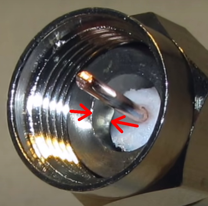
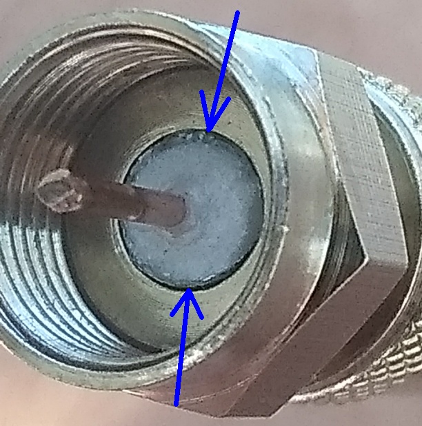
The cable dielectric was not flush with base of F-connector -- many were
significantly 'under' the base (see an example in photo right) and some were 'above' the
base.
After all F-connectors were cut off and replaced by the tech, the Internet problem
improved (but was not gone).
One of the prior Comcast techs, who had just replaced ALL of those F-connectors only weeks ago
(in an attempt to fix the unknown problem), did it wrong, and created this problem.
So a WARNING -- not all cable techs know what they are doing.
And the Comcast tech who made this mistake bragged to me that he had over 15
years of experience working for various cable companies up and down the East
Coast. Even many of the videos on YouTube showing how to install F-connectors
do it wrong (the dielectric is not flush)!
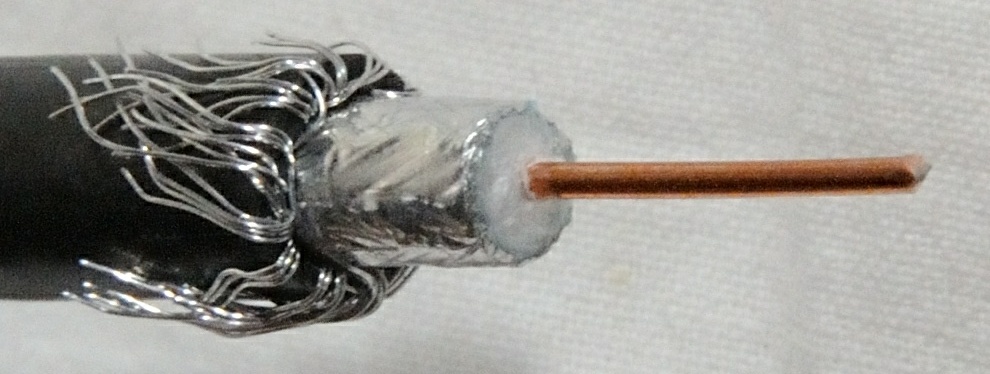
How to check for this issue: Look inside ALL F-connectors for all RG6 cables in your house.
The cables out in the open are easy, but there may be one behind every CATV wall plate as well.
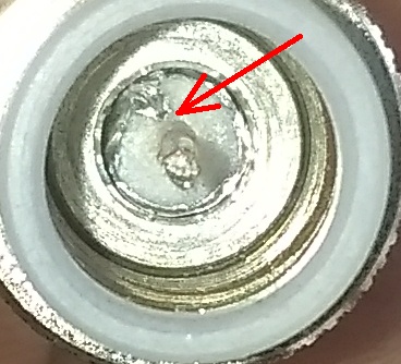
The 'whitish' (dielectric) material surrounding the copper wire sticking out
must be perfectly FLUSH with the bottom of the F-connector (see a 'good' example right)
and you must not see any braiding strands.
Instead, if the 'whitish' material is at all below (example seen in photo upper right) -- or above --
the bottom of the F-connector -- the connector was installed improperly, and may cause
all sorts of problems (allow external RF signals to enter the cable and create 'noise').
Other F-connector 'workmanship' issues to look out for:
- The copper center conductor should stick out around 1/16" to 1/8" above the top
of the F-connector -- and any more or less is a problem to fix.
For reference, the thickness of a nickel is just slightly over 1/16", which is
a great target distance.
- Make sure that none of the foil, or braiding strands, are exposed inside the F-connector
(example seen right). Instead, you should only see the white dielectric and the
center conductor. In the photo right, you can see where the foil
was pushed in and broke instead of being cut -- the TECH was likely using a cutting
tool with dull blades.
- When preparing a cable for adding a F-connector, don't let the blade on your tool
touch (or 'score') the center conductor. 'Nicks' in the center conductor can actually
cause issues (micro-reflections).
- Avoid incredibly tight bends in RG6 cable, which can push the center conductor
through the dielectric and closer to the shielding. This can inadvertently change
the 75Ω electrical characteristics of the cable.
- Never rotate a splitter/post (or grounding block) onto a F-connector to tighten it.
Instead rotate the loose end of the F-connector onto the post/splitter. The entire point is to
avoid spinning the center copper conductor into a connector. This is because
connectors were designed to have the center conductor pushed in/out,
not rotated in/out.
- Gently try to twist the base of any F-connector on the end of any cable. A properly
installed F-connector will be compressed against the cable and will be so tight that it
can not twist. But if it twists at all, the F-connector was not properly installed
-- replace the F-connector.
Anyone can easily replace RG6 F-connectors, but only with the right connectors, tools and techniques.
But do NOT use "twist on" connectors, and do NOT use "crimp" connectors.

F-Connector Compression Kit
|
Instead use only high-quality 'compression' connectors, which create a watertight seal.
On Amazon, you can find tons of inexpensive 'compression' kits
(example)
for around $17 that
includes everything you need to get started (see photo right):
- The compression tool (left, red)
- A handful of compression connectors (middle)
- The cutting tool (right, gray)
Please note that these 'kit' connectors are often intended for 'indoor' use only
(not outdoor use).
The only other tool you will need is a "wire cutter pliers" to cut the RG6 cable to
the proper length, or to cut old connectors off to prepare for a new connector.
Watch:
Video on how to (in general) install F-connectors (on YouTube)
Premium connectors: Because I was going to all the trouble (and frankly, time!) of replacing connectors,
I opted to instead use a 'premium' connector (and not the kit provided connectors). I used
Belden/PPC EX6XLPLUS RG6 Signal Tight
connectors.
TIP: Practice! Take a short cable normally used to connect a cable box to the wall jack, verify it
is RG6 cable, cut off the connectors and practice putting on new connectors using the
'kit' provided F-connectors. Because frankly, you want to know you can reliably
replace F-connectors on a practice cable before attempting to do so on cable behind
a wall plate (with a fixed limited length; very limited retry attempts).
Usage TIP: I personally always use the cutting tool to expose 1/2" of the center conductor
(see photo below), inspect the prepared end of the cable, push on a F-connector until
the dielectric is flush with base
-- and then trim the center conductor to the final distance (thickness of a nickel) above the connector
-- use the compression tool, and the critical last setp -- carefully inspect the result.
The result is that the copper center conductor is always the same precise height
(nickel thickness) above the connector for every connector I make.
Always inspect before AND after:
Before pushing a new F-connector onto a cable,
closely inspect the prepared end (see example photo below)
for any remaining foil not fully cut off, and for any braiding wires that may have
inadvertently wrapped around the center conductor when using the cutting tool
-- as it does happen!
After using the compression tool, inspect the resulting F-connector:
(1) Is the dielectric still flush with bottom of the connector with no foil/braiding exposed?
(2) Is the center copper conductor still a nickel's thickness (1/16" to 1/8") above the
connector? If not, cut the connector off and try again.
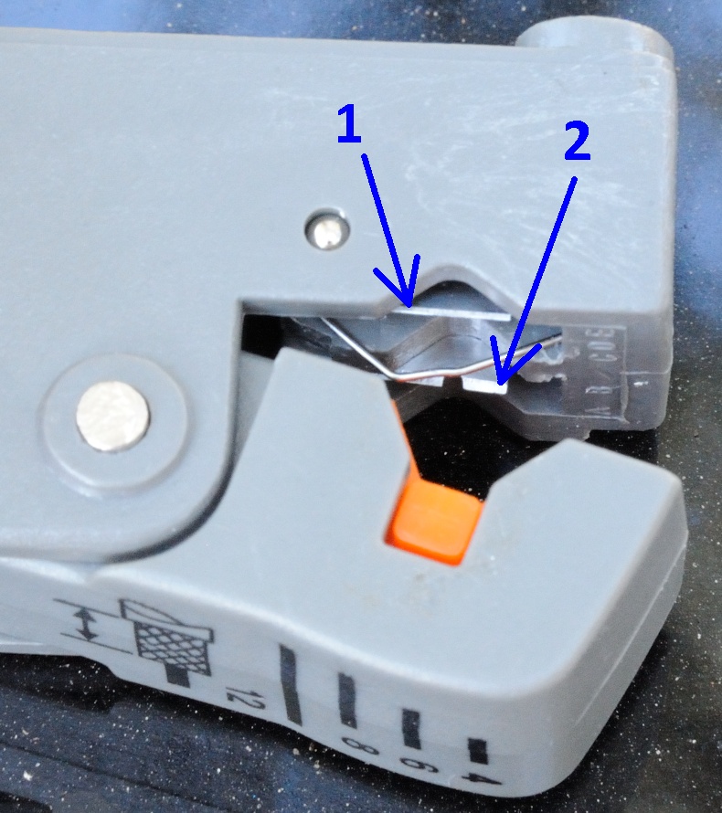
TIP: The cutting tool has TWO adjustable two blades 1/4" apart.
(1) Adjust the first blade so that it cuts only the
outer jacket of the cable (and none of the braiding wire).
(2) Adjust the second blade so that it cuts
most-- but not all -- of the way through the dielectric.
If needed, spin the piece of cable you are cutting off to break any remaining dielectric
(often times, spinning the cutting tool ends up doing this for you).
Important: The second blade must NOT touch/score the center conductor. This is very easy
to accidentally do, especially you have adjusted the blades for one cable and then
move to a second brand of cable!
So if you are just starting out, practice (if you have enough cable). Prepare the end
of the cable and instead of putting on a connector, cut back more dielectric and verify
that the center conductor is not scored (you can tell by running your fingernail over
the center conductor).
Some tools even have a notch in the second blade to help avoid this problem.
FYI: A Comcast TECH (employee) in October 2021 (in Georgia) was using
"PPC Perfect Flex" RG6 cable, which looks to be a tri-shield cable.
Loose connectors allow for RF ingress (noise) and can cause
all sorts of intermittent cable modem problems.
Any connector that is NOT fully screwed onto the corresponding post (around 1/4")
or is not 'finger tight' is considered a "loose connector".
- If you screw a F-connector onto a post and it 'stops' and is 'tight' early,
something is very wrong. Find out why. Instead, the connector must screw on
completely (around 1/4 inch).
- Make sure that all cables (F-connectors) are screwed onto posts a strong finger tight,
as any loose connectors can actually cause RF ingress problems.
- A cable connected to a wall plate, but connected to nothing -- is also bad. The
exposed (loose and unconnected) F-connector can act as an antenna, allowing for RF
noise to enter the system. If there is no device connected, there are
inexpensive 'cable termination caps' that can be screwed onto unused posts.
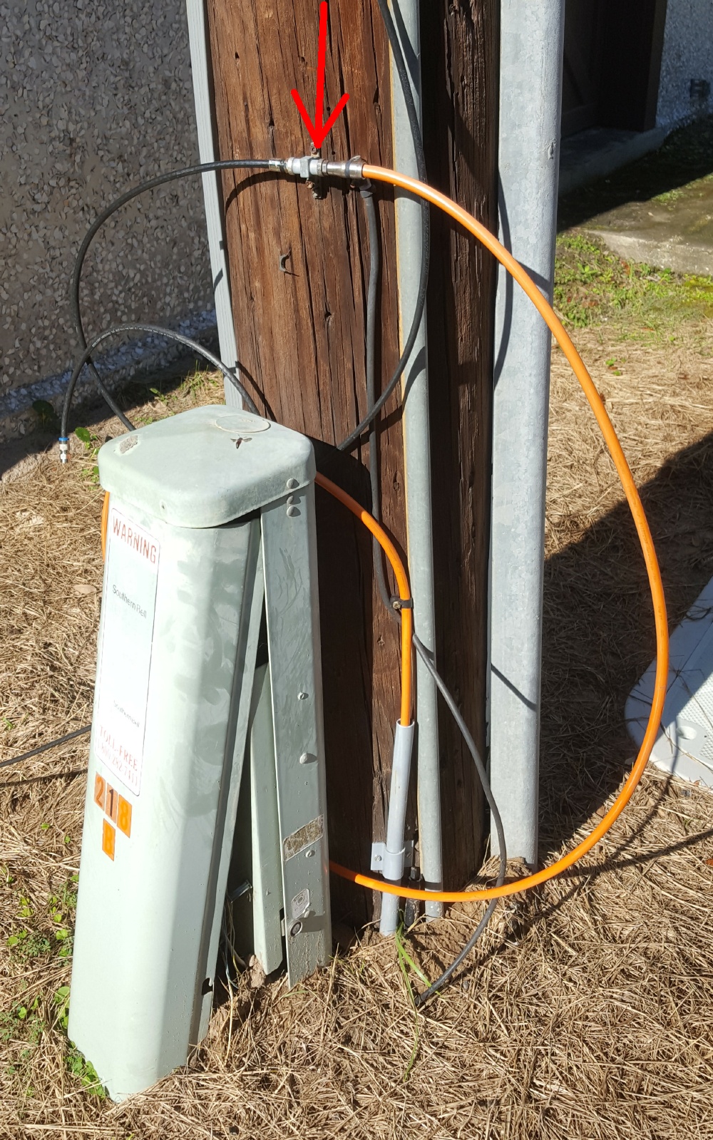
Loose connector at ground block
|
An example: It is not uncommon in 'overhead' cable installations to see
a 'ground block' at the bottom of telephone pole, where one cable comes down
the pole from the 'tap', and another cable is the run/feed underground to a house.
In the example seen right (red arrow), the black RG6 cable comes down the pole from the
tap, and the orange RG11 feeds a house.
However, the problem at this location was that the orange connector, while
seemingly 'tight' on the ground block, was NOT actually fully screwed onto
the ground block. There was a couple of grains of sand (or something) preventing
the connector from screwing on fully.
Symptoms: The cable modem experienced lots of intermittent T3/T4 errors,
and modem upstream power intermittently spiked.
And the cable modem log was full of "RNG-RSP CCAP Commanded Power in Excess of
6 dB Below the Value Corresponding to the Top of the DRW" and "Dynamic Range
Window violation" warnings.
TIP: Get a good feel for how far (around 1/4 inch) a connector must be
screwed onto the corresponding post -- do NOT rely upon a connector feeling
'tight' to indicate that a connection is fully screwed in --
because it may be tight but NOT fully on.
Look into any F-connector. The distance from the base of the connector to the
top of the connector (around 1/4 inch) should be the distance that the connector
screws onto a post.
Inspect EVERY F-connector, especially those behind wall plates:
I once found a connection behind a wall plate (for a modem having problems) just barely
touching, and the last person to touch/inspect that was the Comcast cable tech! Do NOT
assume that a connection is 'good' just because a cable tech was the last person to
look at a connection. Instead, take all connections apart, inspect, and put back together.
WARNING: Only consider using a 'powered amp' after inspecting ALL F-connectors in your house
(even those behind wall plates) and fixing any problems found -- as fixing all bad connectors
first may alone improve signal quality enough that a powered amp is no longer needed.
TIP: Use a powered amp only AFTER you have solved your cable modem problems! Because
the one disadvantage of using a powered amp is that any 'noise' being generated on any run (inside
the house) will then only be amplified and possibly interfere even more with your cable modem.
If you are unable to solve your 'noise' problem, do NOT use a powered amp. In fact, by sticking
with a non-powered splitter, you are adding 'attenuation' to 'noisy' runs, making it much harder for
the noise to cause problems with other runs in the house (like your cable modem).
BUT, once you solve any noise/cable problems, using a powered amp is a great way for all devices
in the home to obtain the best power levels that are possible.
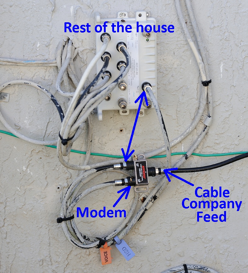
A 'typical' CATV/modem installation in FL
|
The 'typical'/recommended CATV/modem installation:
At the demarc box/location on the side
of the house, the feed from the cable company goes into a two-way splitter that feeds
(1) the modem and (2) the rest of the house via a passive 2/3/4/6/8 way splitter.
An example of this configuration is seen in the photo right
(in Florida it is very common for these devices to be mounted on the outside of the house, exposed):
For most homes, this configuration will work best. But if you home is running
into problems with signal strength (too many cable boxes), consider using a powered amp.
A new way: Improving CATV signal quality / SNR: The CATV industry now makes
very affordable 'lossless' 8-port active splitters / powered amps
for home use, with built-in cable modem support.
TIP: Only use the new amps when really needed, when either (1) downstream signal levels
must be improved, or (2) when two-way VoD cable boxes are having trouble working.
Older 'one-way' cable boxes will often times work just fine behind a passive splitter.
Using a powered amp is a great way to ensure that all two-way cable boxes
(like Comcast X1) have the best chance of working properly in a large home
where all cable boxes are two-way boxes.
The key advantage these new amps have (over amps made years ago ago) is that these
new devices are 'smart' and have NO power loss in both the downstream
(52-1002 MHz) and upstream (5-42 MHz) paths, which is critical for DOCSIS
devices, like VoD set top boxes, to work.
Many older amps (still sold today) only amplified the downstream, and left the
upstream with full (lots of) power loss, which could negatively impact VoD cable
boxes. These old style amps have "passive return" and should now be avoided.
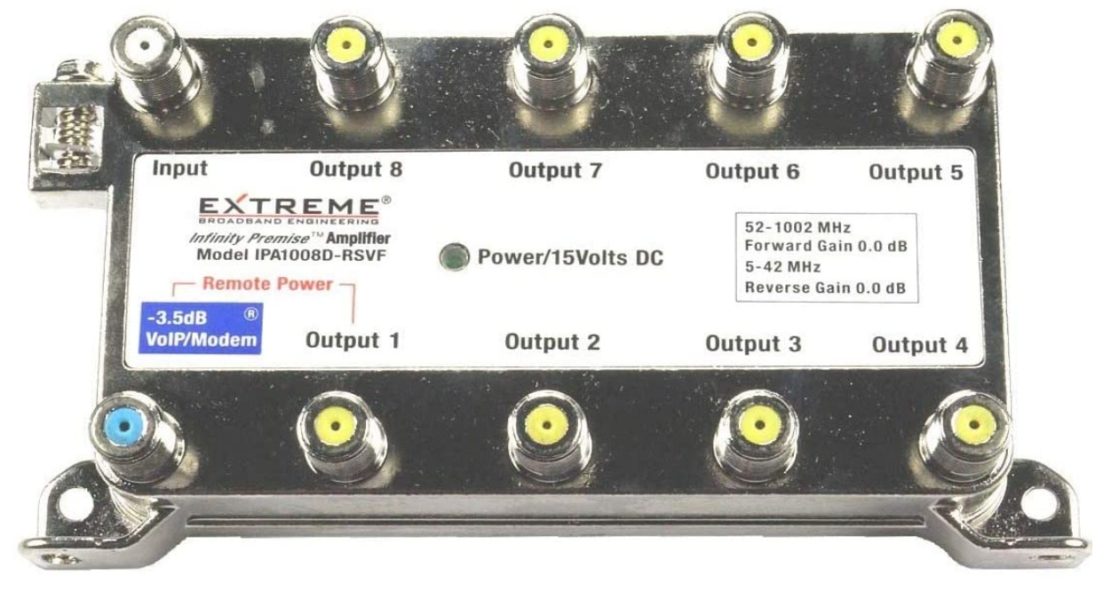
Example: One example of a new-style amp is the
"Extreme Broadband IPA1008D-RSVF - 8 Way Splitter"
(seen below right) for around $45 to $60 on Amazon.
This is the exact brand/model that my cable company (Charter/Spectrum) in North Carolina
installed.
So if the IPA1008D-RSV is 'good enough' for the cable company itself to provide and use,
I feel confident enough to buy/use elsewhere (and I have).
Remotely powered:
The IPA1008D is remotely powered via a 'power injector' added to one of the cable runs
in the house (and then that powered cable run is connected to 'Output 1' on the amp).
Modem/VoIP port:
By design, ONE passive port of the amp remains active after a power
outage and all other active ports 'go down'. This one (and only)
passive port trades around 3.5 dB (of loss) for this feature/functionality -- so that
modems with VoIP remain online and can still place phone calls during power outages
(e911 compliance).
It is strongly recommended that you connect your cable modem (regardless of having
VoIP, or not) to the passive port on the amp. Because this port also bypasses the diplex
filter in the amp (operating at 5-42 MHz) in case your cable company has expanded
the MHz range used for Internet upload channels.
When the cable industry moves to DOCSIS 4.x, it is expected that the
MHz range used for 'upload' will expand well past 42 MHz.
While cable modems WILL (should) continue work on any amplified port (but maybe with limited upload speeds)
the noise on the un-amplified return path on the passive port 'should' be
slightly better (less) than the noise on the amplified ports -- as this avoids
the "10.5 dB loss + 14 dB gain" return path (see below).
I say 'should' because the critical SNR value that would definitively answer
this question (how much of a noise difference) is in the CMTS and is not accessible to us.
In fact, in Maryland, a Comcast tech installed a PPC EVO1-9-U/U and connected the
cable modem to one of the amplified ports (not the passive port) -- so yes, it works.
Unused ports: Be sure to put a '75 Ohm Terminator cap' on any unused amp output ports.
This helps to stop unwanted RF ingress (that can once again impact the cable modem).
How these new amps work:
A block diagram representing (generally) how these new amps work
(source):
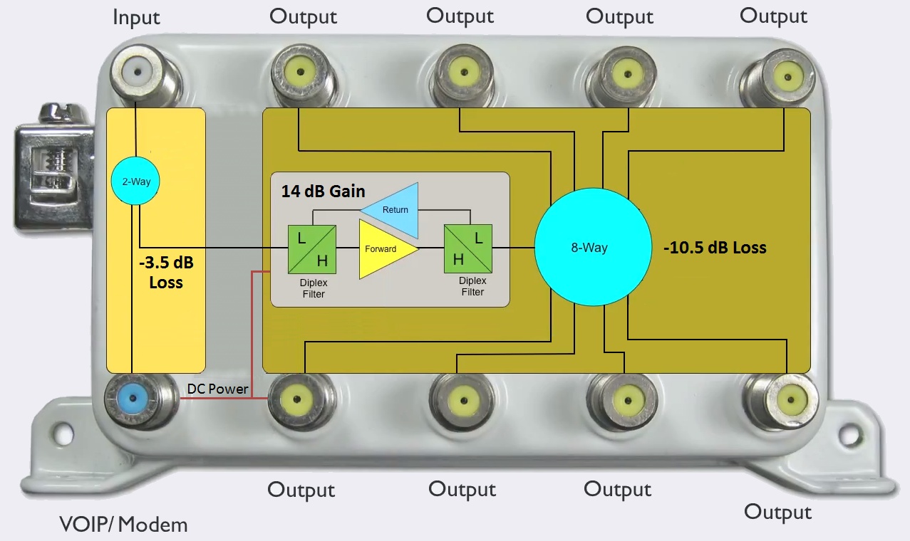
Notice that these new amps are just an unamplified 2-way splitter (left block) followed by
a bi-directional amplified 8-way splitter (right block; on one leg of the 2-way splitter).
The bi-directional amp amplifies only "H" (high) frequencies (52-1002 MHz) in the downstream
direction (cable modem download) and only "L" (low) frequencies (5-42 MHz) in the upstream/return
direction (cable modem upload).
The "VoIP/Modem" port bypasses the diplex filters -- a good thing if you have a cable modem
that operates outside of the 'standard' upload frequency ranges.
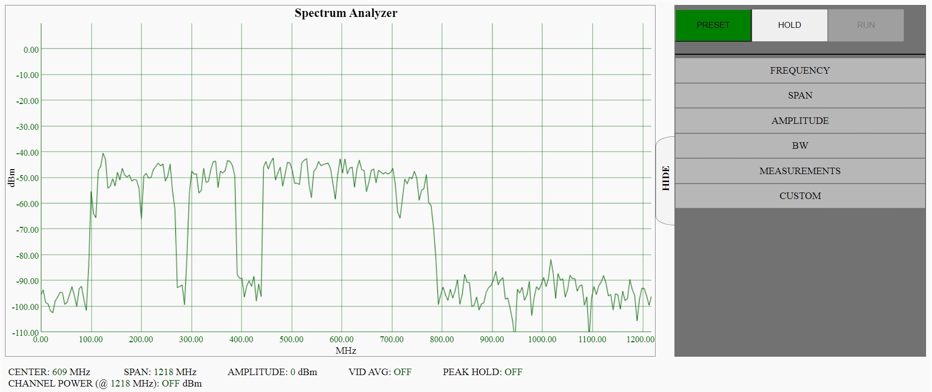
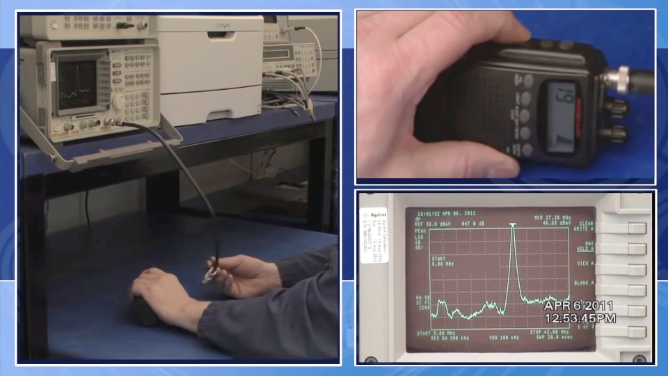
Some cable modems (often based on the Broadcom chipset) expose a 'Spectrum Analyzer'
interface on port 8080.
Spectrum Analyzer:
To see if your cable modem provides this feature (but your cable company may also intentionally hide it;
Comcast typically HIDES it),
use a web browser to access port 8080 of your cable modem
(often http://192.168.100.1:8080, or http://192.168.0.1:8080) and you may
see the following (after clicking on the 'Run' button):
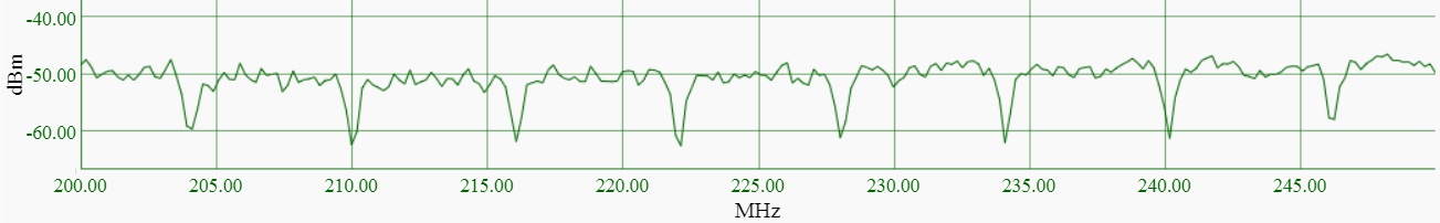
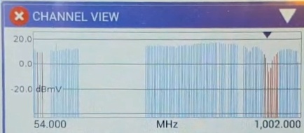
Seeing QAM channels:
And in fact, when zooming into 50 MHz of spectrum and using the 'peak hold' feature, the
6 MHz wide QAM channels become obvious:
TIP:
Or Google your modem model number and "Spectrum Analyzer" to see if anyone has posted instructions
on accessing the built-in tool (some modems may use a different port number).
Why so valuable: If your modem has this capability, this is yet another
great way to see and confirm if there is 'suckout'. Just zoom into the frequencies used
by the cable modem for Internet downstream channels, and again use the 'peak hold'
feature.
A cable modem reboot CAN sometimes 'solve' a problem, even though the root problem still
remains!
Watch out: During a modem reboot, the cable modem may negotiate a different
set of channels to use, which in turn may avoid a problematic channel (frequency),
which means the problem ultimately remains and might come back after yet another modem reboot.
I ran into this at one location where sometimes Internet connectivity was horrible, but
at other times, it was perfectly fine. It turns out that when Internet was horrible, the
cable modem was using a specific channel that had a ton of uncorrectable errors, and when
Internet was great, the cable modem was not using the problematic channel.
Ultimately, the root problem was tracked down to a single bad cable that was negatively
affecting a very specific MHz range (the single channel). Once the cable
was replaced, the root problem was fixed.
TIP: If possible, in the cable modem (via web page), set the starting frequency
that the cable modem uses to search for downstream channels. After every modem reboot,
verify that the modem is still using the same download/upload channels. This will
allow you to more easily compare if a change you made actually helped
(or if the improvement was due to the modem using different channels).
Use the cable boxes in your house as a poor man's power level meter. Use the boxes to identify
the cable runs in the house that are experiencing 'too much' unexpected loss --
then find out why, and fix.
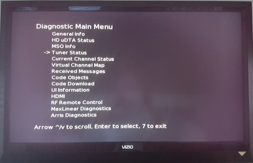
Diagnostic Screens:
Most cable Set Top Boxes (STB) have an extensive set of diagnostic screens. Just Google
'diagnostic screen' and the model number of your cable box to find out how to access these
screens.
Here in Georgia (Comcast), for my cable boxes, I just need to press/hold '0' on the
remote for around five seconds to get the diagnostic screen seen top right.
In Florida (Spectrum), same thing, but with the 'info' button.
Or, for Comcast X1 boxes, hold 'Exit' for five seconds, then press the down
arrow (below ok) two times, then press '2'. Seems very timing sensitive, so repeat
if needed.
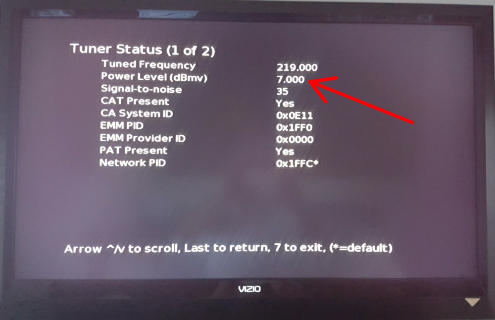
How to use for troubleshooting: Tune every cable box in your house to the
SAME channel and then go into the "Tuner Status" diagnostics page (example seen
bottom right).
The "Power Level" number for all STB in the house (when tuned to the
same channel -- verify that the "Tuned Frequency" displayed is the same)
should be fairly close (within a couple of dB) to each other.
This test only works when all runs in the house are connected to the
same X-way splitter / amp.
You then try to account for differences in power levels seen in the STB
diagnoistic screens between runs/rooms by comparing the difference seen to the
expected loss (see the next section) caused by differences in splitters and
cable run length between the two runs/rooms.
When the power level difference is not fully explained by differences in
splitters and cable length between the two runs, then you have something
to investigate.
The goal:
The goal is to find cable runs that are way below the expected dB level,
as compared to all other runs -- and then find out why, and fix the issue.
An example: In my home, one room really stood out in a bad way -- the Power Level
was 7 dB below all other rooms.
During my inspection of all F-connectors behind wall plates in the house, the
problem in that one room became obvious:
- There was a splitter behind one of the wall plates feeding an unused second
location in the same room. So the splitter was removed.
- All F-connectors behind the wall plates in this one room had the same very serious
problem -- the dielectric was WAY below the base of all connectors.
So all F-connectors were replaced.
Once these two fixes were made in this one room, the "Power Level" reported by the STB
tuner diagnostics screen was 7 dB higher (on par with other rooms in the house)!
But more importantly, these bad F-connectors were almost certainly having some
impact (micro-reflections, etc) on the rest of the house (and impacting the cable modem)
-- so that problem was fixed.
Cable Loss: In general, the attenuation (dB loss; left Y-axis)
(source)
you can expect in RG6 cable (by cable length; various colored lines; see right Y-axis)
by frequency (X-axis) is:
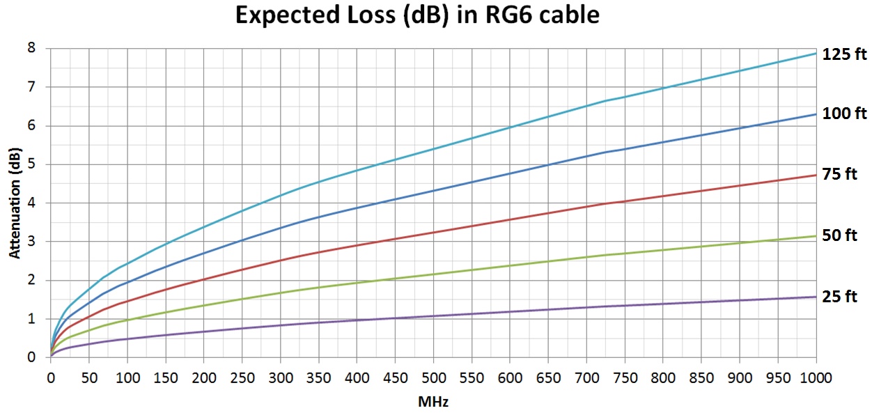
For other cable lengths not listed, pro-rate the value for any other cable length that is listed.
So for a cable run of 200ft, double the number obtained from the graph above for 100ft, etc.
Notice that 'expected loss' changes depending upon the frequency (channel) being used.
This is because higher frequencies attenuate (lose energy) more quickly than lower frequencies.
TIP: A great rough linear 'guestimate' for the 100 ft curve, for any MHz above 100,
is 2.25 dB plus 1/2 dB for every 100 MHz over 100 MHz. The same formula, but
reworked for easy 'mental math' is to take the MHz, divide by 100 (move decimal two places),
subtract one, divide by 2, and add 2.25.
For example:
(1) for 200 MHz, think (2.00-1)/2 + 2.25 = 2.75,
(2) for 600 MHz, think (6-1)/2 + 2.25 = 4.75,
(3) for 750 MHz, think 6.5/2 + 2.25 = 5.50.
This answer is for 100' of cable, so then take the result and pro-rate
for your cable distance.
|
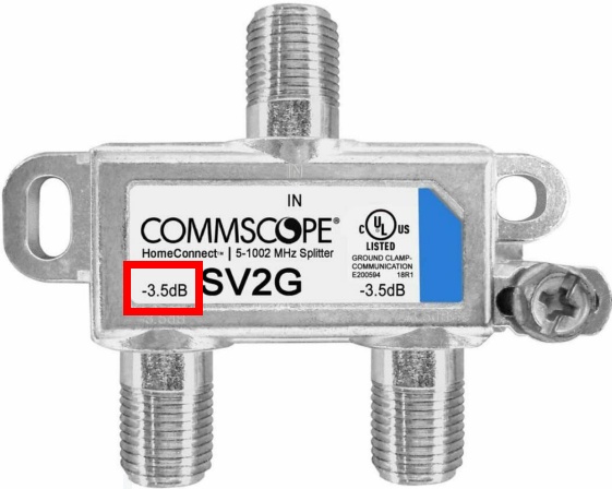
Splitter Loss: The dB loss (between IN and OUT ports) caused by using a passive
splitter should be printed on each output port of the splitter (example seen right).
In general, expect the loss for each output port of a splitter to be 'around':
| Splitter | Loss |
| 2-way | 3.5 dB |
| 3-way (balanced) | 5.5 dB |
| 4-way | 7.0 dB |
| 6-way (balanced) | 9.0 dB |
| 8-way | 10.5 dB |
Please note that all splitters also act as 'combiners' in the reverse path, with the
same dB loss between OUT and IN ports. For example, with a 2-way splitter, expect
3.5 dB loss in the downstream (cable company to house), but also expect 3.5 dB
loss in the upstream (house to cable company).
Also note that the cable connected to the "IN" port always has the signal coming from
the cable company, and that cables connected to the "OUT" ports always sends that
(attenuated) signal to other devices (STB, cable modem, another splitter, etc).
|
The history of Comcast TECH visits (actually, all seemed to be contractors, not Comcast
employees) trying to fix the Internet problem at my one location in Georgia (that caused
this paper to be written) are as follows:
There were several prior visits over the years that failed to resolve the problem.
I even went through three different cable modems (and different vendors) trying to
fix the problem, and all three modems had the same problem. I
finally wised up and thought 'This is crazy, why am I paying for bad Internet -- I
am just going to keep reporting the problem to Comcast until they find and fix the problem'.
At this point I started documenting everything that happened.
- 2020/06/12: The TECH blamed a bad underground cable run from the
pole to the house (said landscapers must have hit the underground cable).
A temporary 'above ground' cable was run that day, but it was replaced days later with an underground run
by a different crew. Interestingly, instead of the previous RG6 underground
run to the house, a thicker RG11 (a cable with a slightly lower attenuation) was installed.
The problem remained.
- 2021/05/19: The TECH blamed a bad port on the tap up the telephone pole. The house
run was moved to another port on the tap. Comcast actually charged me $100 for this visit, which
I finally got refunded.
The problem remained.
- 2021/05/29: The TECH blamed splitters in the demarc box on the side of the house.
Both were replaced. One was a 3-way splitter feeding (1) the modem, (2) the X1 cable box, (3) an
8-way splitter feeding all other one-way cable boxes.
The problem remained.
- 2021/08/18: The TECH proactively replaced all F-connectors in the demarc
box on the side of the house. A text from the TECH said "all that was done was new fittings".
The problem remained.
But see 10/01 below -- all F-connectors were installed improperly. Also, when I looked in
the cable demarc box, I found that the line feeding the entire house was 100% loose -- touching
and not even screwed together at all. The TECH clearly missed putting a connection back
together!
2021/09/09: The TECH never showed up for the appointment.
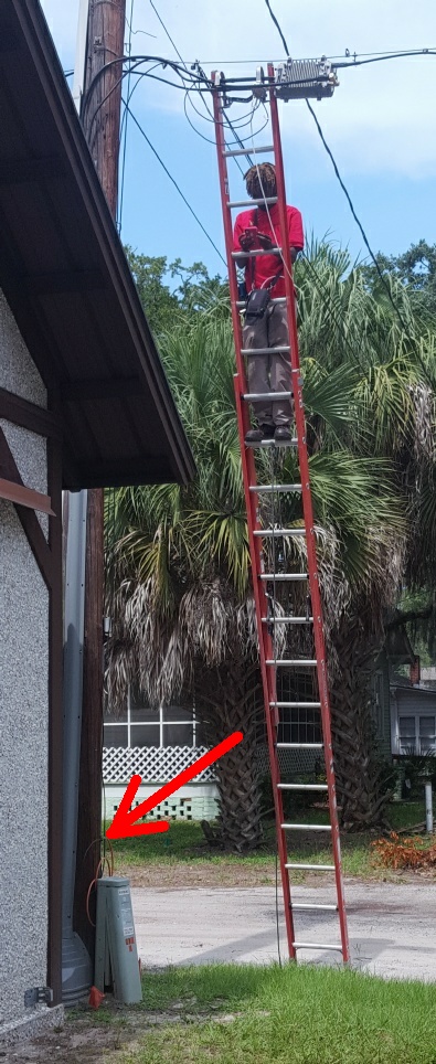
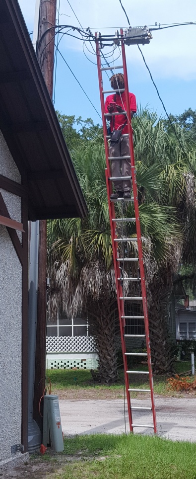
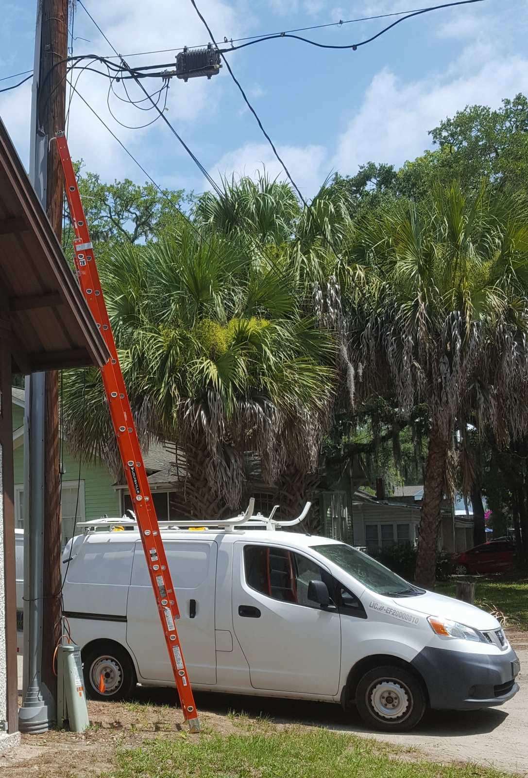
- 2021/09/11: The TECH blamed "suckout" and "low mEr" at the tap
on the telephone pole (see photo upper right).
He submitted a ticket to Comcast to get that fixed. The graphs far above in this paper
show an improvement in signal levels. The next day, Internet seemed better and was better for
weeks (but I also installed a lossless amp at the exact same time, which improved SNR),
but the problem ultimately 'came back' in late September.
Oh boy, doing it wrong: Notice the TECH (photo upper right) hooked the ladder on
the actual cable lines, instead of hooking the ladder (only inches higher) on the
much stronger messenger cable. Also the TECH was testing an unused port on the tap
instead of the port feeding my house.
- 2021/10/01: The TECH blamed improperly installed F-connectors in the demarc box.
Major problems were found (dielectric not flush) with all F-connectors
on all cables in the demarc box on the side of the house, and ALL were replaced. The TECH said
it was so bad that he was surprised that the X1 cable box was even functional. We noticed a recent
brand new problem of 'blocking' on TV channels that also went away after the F-connectors
were replaced, confirming the impact of the bad F-connectors.
Absolutely crazy since these F-connectors had been inspected and replaced (apparently improperly)
only weeks earlier by another TECH on 8/18.
The problem ultimately remained.
I later found a near short (exposed foil) in one of the connectors put on by
the new TECH. Not at all surprising since I watched first-hand as the TECH
used the compression tool and then did NOT inspect the resulting connection
for defects. If he had, he would have found his own mistake in workmanship.
Overhead Cable Tap
|
2021/10/08: The TECH never showed up for the appointment.
2021/10/09: I spent the next several days tracing
cable runs, inspecting ALL connectors everywhere, and replaced several bad
connectors. See further below for more details.
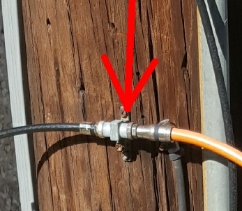
- 2021/10/12: FINALLY, a Comcast TECH (employee) came out (not a contractor), who
said they come out when too many contractors are sent to the same location and are
unable to fix an issue. The TECH focused on the telephone pole;
found that the ariel connection at the tap was loose
(see photo right);
replaced all connectors at the pole for the drop line to the house (one high; two low);
tested signal quality at each step; tightened all connections using a wrench; worked
back to the demarc location; eventually ended up at the modem location inside the house;
tested and said everything looked good. At first, Internet seemed better, but
the problem remained.
-
2021/10/31: The local "Technical Operations Supervisor" came out (I was not at the house)
and said that one of the runs in the house was causing noise ingress.
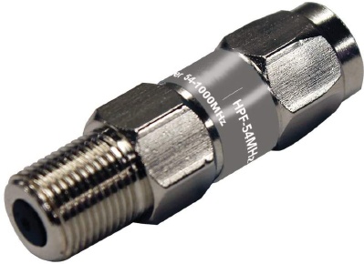
A hi-pass 'filter'
was placed on that one run -- so that any ingress on this run (causing interference
in the frequency range used by the cable modem) would be blocked.
I presume what the Supervisor installed was an "in-line high pass coupler barrel
adapter 54-1000 MHz filter" (example seen right) on the 'noisy' run that
had a one-way cable box. The filter
blocks the frequencies below 54 MHz (which are used by modems and two way cable
boxes). In this way, the noise ingress from that one run is blocked from impacting
the cable modem upload channels.
2021/11/21: The problem went away for a short period of time, but I was
able to remotely confirm that the problem still remained!
2022/01/19:
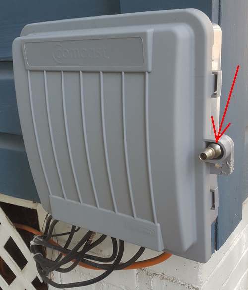
I came back to the house to find that the Supervisor had placed a 'lock'
(see arrow in photo right) on the demarc box, which was a jerk move because inside
that box is MY amp, and it prevented me from further testing on my own. I asked
the Supervisor to remove the lock, and she agreed (in writing), but no one ever came
to unlock the demarc box!
2022/05/29: I finally bought the special $10 tool on Amazon
that allows me to lock/unlock the demarc box myself. So once again, I connected
the cable modem directly to the Comcast demarc location (bypassing ALL house wiring)
and confirmed that the problem still remained, even with all house wiring disconnected.
I still experienced regular cable modem T3 drop outs. A meeting with the local
Supervisor was scheduled.
tech replacing drop cable
|
- 2022/06/11: The local "Technical Operations Supervisor" was supposed to come
out a second time, but instead sent a regular contractor out, not even a Comcast employee.
The tech arrived to find me testing and my modem connected directly to the Comcast demarc location
(bypassing all house wiring) and still experiencing significant Internet drop outs.
I explained a brief history of the problem and stated to the tech that even when I connected
my modem to the base of the telephone pole, I still experienced problems (eliminating the
underground run from the telephone pole to the house demarc location as the problem), and that
this meant that the problem was somewhere at the telephone pole on up, and I stated that I wanted
both the TAP (that a prior tech said had a bad port) and drop cable
(the line running from the TAP to base of the telephone pole) replaced.
The TECH explained that only Comcast itself (and not him, a contractor) can replace the TAP,
but said that he would do the only thing that he could do, which was to
replace the drop cable.
So this tech:
(a) replaced the drop cable from the TAP to the bottom of the telephone pole,
(b) replaced the ground block at the bottom of the telephone pole,
(c) replaced the connector on the underground run to the house (at the ground block), and
(d) moved the drop cable to a different port on the TAP (to a port that surprisingly a prior tech had said was bad).
I also watched this tech incorrectly spin a ground block
onto the end of the cable, instead of turning the cable onto the end of the
ground block. Argh!
So, are things finally 100% fixed? YES! The number of critical cable modem errors
is now nearly zero. Compared to before, with several critical errors every hour, that is a huge improvement.
The ultimate core problem at this location was either (1) a bad RG6 drop cable
(the run from the TAP at the top of the telephone pole to the ground block at the base of the telephone pole),
or (2) a bad ground block at the base of the telephone pole.
The F-connectors on the drop cable were replaced numerous times over the years by various
techs -- without helping -- which excludes bad F-connectors as the root problem.
The bottom line: Why did it take years and 10+ tech visits to fix this problem?
It is clear from all the tech visits documented above, that what cable techs
do and say is full of contradictions. It sure seems like a lot of techs (contractors) know
just enough to sometimes help, but also have some 'trade craft' / quality issues.
A house next door works just fine:
As an interesting side note, a second location/home that is just 200' away and on the same amp
up the telephone pole (but on a different leg off of that amp, and a different tap) never
has any of these intermittent Internet issues. This strongly suggested that the problem was NOT
within the cable company infrastructure.
An interesting long history of problems with Comcast:
In 2005 we signed up for Internet from Comcast, but every time it rained, the Internet would
drop out for hours (sometimes even the rest of the day). Comcast could never find the problem.
Out of desperation, in 2008, we switched to slower DSL, only to get reliable Internet -- and it worked! But
in 2017, due to much faster cable Internet speeds, we switched back to Comcast and tested. The
'rain' problem was gone. But we noticed a new very annoying intermittent
cable modem issue. Over the years, I have tried three different cable modems (different vendors),
and they ALL experienced the same intermittent problem.
How one problem was fixed:
After the TECH failed to show up for the 2021/10/08 appointment, I had
had enough and spent the weekend finding/inspecting ALL cable runs everywhere myself,
and found numerous problems (but not the 'core' problem):
- A connector at the ground block at the telephone pole for the run to
the house was 'tight' but NOT fully screwed in. After fixing, cable modem
upstream power stabilized for a time.
- The TECH on 2021/10/01 had replaced a ton of connectors, but actually
left with a replacement connector in a virtually "shorted out" condition (see photo
right). The foil was not cut properly and wrapped around the dielectric and was a
hair way from touching the center conductor.
- I inspected ALL connectors behind wall plates in the house and replaced
those connectors where the dielectric was not flush with the base of the connector.
The biggest lessons I learned:
The number of tech visits (10+) to this GA location without a resolution
was insane. Even the local Comcast
"Technical Operations Supervisor" came out and did not find the problem!
What I learned:
- Don't assume that there is just one problem to fix, because in reality, there will
very likely be multiple issues to fix. And at this location in Georgia,
there were problems with both the cable company and with wiring inside the house.
- If a couple of tech visits don't solve your problem
immediately, insist on a subsequent visit that ALL cables, ground blocks,
etc, all the way from the TAP to your house demarc location, be replaced!
If I had been more assertive and requested this, my Internet problems would have been
solved years ago.
A BIG clue: Upload channel power quality / STABILITY is critical:
Cable modem upload channel power should remain very consistent throughout the entire day.
When you see cable modem upstream power fluctuate/spike a moderate amount
(I was seeing 3 to 10 dB) during the day, that is NOT normal, and indicates
a problem to find. The likely cause is a bad cable, somewhere, so start
inspecting cable runs and connectors -- everywhere.
Cable TECH's are making a ton of mistakes: Even when the TECH who complained
about the quality of connectors made by a prior TECH, he still left with a
replaced connector in a virtually "shorted out" condition.
I even found a connection behind a wall plate completely loose (touching, not
screwed together), and the last person to touch that wall plate was a
Comcast cable tech.
Inspect all connectors everywhere: It is NOT enough that a connector just be tight. Instead,
remove the connector, inspect it (is white dielectric flush with base of connector), and screw it
back on, ensuring that the connector screws on about 1/4 inch, and tighten (a strong finger tight).
During this inspection, I found (and replaced) many connectors behind
wall plates where the dielectric was well above/below the base of the connector
The original house builder/electrician did this many years ago and was clearly
not very skilled!
How one issue was found: I hooked my modem up directly to the cable demarc location
at the side of the house (via a 100' cable) and still had the intermittent connectivity
problem. That pointed the finger directly at the cable company.
The connector at the ground block at the bottom of the telephone pole (red arrow in
photo right) was 'tight', but not fully screwed onto the ground post.
Do not underestimate the negative impact of loose (or tight, but not
fully screwed in) connectors!
"The number one thing we actually see as a 'craft error' is that the connector
is not properly tightened onto the port".
Rich Maroney, Product Line Manger Coaxial Cable, PPC.
[Source: YouTube video]
A final word:
Most cable modem problems can ultimately be traced back to ONE issue: something cable
related (a bad cable, a bad connector, etc) either inside the house, or in the run
from the cable company to the house. If you are willing to spend some time and effort,
you should be able to use the process of elimination to find the location of the root cause. And when
in-house wiring is to blame, fix the problem yourself (and when not, call the cable company to fix).
I have done my best to make this paper as easy-to-understand, no-nonsense, informative
and accurate as possible -- so that YOU can hopefully fix your own CATV problems.
But it has grown far larger than initially intended.
Did you find an error, a typo, or have a suggestion on how to improve this paper?
Did this paper help you? Do you disagree with any recommendation?
Let me know...
Use this contact form to contact the author of this paper, Jerry Jongerius.
|
Some images and text are copyrighted by their respective owners and are reproduced
in this paper under Title 17 Section 107 (Fair Use) of the copyright code.
The rest of this document is Copyright © 2026 Jerry Jongerius
As an Amazon Associate I earn from qualifying purchases.
|

 YouTube video showing "suckout"